A responsive 2D robot arm simulation
Published 07 Sept 2026 · Updated 12 Sept 2026 · 31 min read
How to build a responsive 2D simulation of a 2DOF robot arm with Three.js through Threlte and Svelte.
On this page
The simulation built in this post runs in the browser and is responsive, automatically adjusting to the viewer’s screen size. A 2DOF arm is a useful starting point because two links and two joints are enough to make inverse kinematics, reachable targets, and different elbow configurations visible without a large amount of code. Once these ideas are clear, the equations and code structure can guide extensions to robot chains with more links or different link lengths, although longer chains need more advanced inverse-kinematics methods. Keeping the visualization in 2D also lets us learn Three.js concepts such as cameras, meshes, coordinates, pointer events, and render loops before adding depth for a 3D version.
The arm follows a target point that you move with your mouse or pointer. On a touch device, you can tap or swipe across the simulation instead. Each new target position is passed to the inverse-kinematics calculation, which finds the two joint angles needed to guide the robot arm toward that point. The red marker shows the current target. Here is the final result:
Move your pointer across the simulation to guide the arm. On a mobile device, tap or swipe across the simulation instead. The red marker is the target point.
The graphics come from Three.js, the component framework is Svelte, and Threlte acts as the bridge that lets the simulation create Three.js objects declaratively and update them from reactive state. Tailwind CSS is used to style the application. The initial implementation used @threlte/core 8.6.0 and @threlte/extras 9.21.1 with Svelte 5.57.0, Three.js 0.185.1, and Tailwind CSS 4.1.11. Threlte expects Three.js as a peer dependency, so it does not install a separate copy for the scene. The complete simulation code is available at the end of this post.
Understand the 2DOF robot arm
Before connecting the mathematics to Three.js, it helps to understand the robot we want to control. The arm has two degrees of freedom, or 2DOF, because it has two independently rotating joints. The first joint changes the direction of the first link, and the second joint changes the direction of the second link relative to the first one.
In this article, Joint 1 is the base joint, and Joint 2 is called the elbow. “Elbow” is a descriptive name for the joint between the two links, not a third joint or an extra degree of freedom. We also use “arm tip,” “second link’s tip,” and “mathematical tip” to mean the same point: the endpoint used by the kinematic equations. In the simulation, the orange pieces beyond that point form a visual gripper, which is the arm’s end effector. The red marker follows the mathematical tip, not the outer edge of the gripper.
The arm is drawn on a flat - plane. The first link has length and angle . The second link has length and relative angle , so its direction in the world is . The point we want the arm to reach is the target , and its distance from the base is .
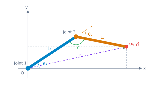
Schematic of the 2DOF arm geometry used by the forward- and inverse-kinematics equations. The drawing is illustrative and not to scale.
Forward kinematics starts with the two joint angles and calculates where the arm ends:
Inverse kinematics solves the reverse problem. We start with the desired target and calculate the joint angles that can reach it. First, calculate the target distance:
To use the law of cosines, introduce , the interior angle at Joint 2 in the geometric triangle:
For the configuration shown, and are supplementary. Therefore, and :
The denominator is positive because link lengths are positive, so the numerator determines the sign of the cosine:
- If , the cosine is positive.
- If , the cosine is zero.
- If , the cosine is negative.
This tells us whether the magnitude of the relative angle is smaller than, equal to, or larger than 90 degrees. It does not tell us which side of the base-to-target line the elbow uses, because positive and negative angles have the same cosine.
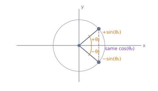
Mirrored positive and negative angles have the same horizontal cosine projection, but opposite vertical sine projections.
The sine magnitude comes from :
The square root gives a positive magnitude. Choosing the positive or negative sign creates the two mirrored elbow configurations:
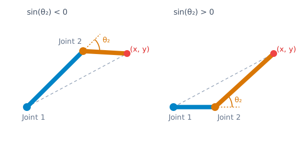
The same target can have two valid elbow configurations. The cosine of is the same in both, while the sine has the opposite sign.
Both signs are valid mathematical solutions for a reachable target. There is no single correct choice unless the robot has an additional rule, such as a preferred elbow direction or a joint limit. In the simulation, the arm is already in a pose when the target moves, so the simulation calculates both possibilities and keeps the one that requires the smaller change from the current pose. We’ll see this later after the equations have been connected to the visualization.
The arm cannot reach every point in the plane. Its farthest distance is , when both links are stretched in the same direction. Its closest distance is , when the longer link folds back toward the shorter one. A practical implementation clamps targets to this reachable range before using the equations.
These equations describe the robot independently of any graphics library. We now create the Three.js visualization with Threlte, then connect this mathematical model to the meshes and pointer interaction.
Create a Threlte canvas
A canvas is the browser’s drawing surface, where Three.js renders each frame. Threlte’s Canvas creates the renderer and the place where the robot is drawn.
The simulation uses two Svelte components. RobotArm2DOFMouseFollower.svelte owns the Canvas wrapper and its loading state, while RobotArm2DOFMouseFollowerScene.svelte contains the robot and its behavior. The page places the wrapper inside a responsive container like this:
<div class="aspect-4/3 w-full"> <RobotArm2DOFMouseFollower /></div><script> import { onMount } from "svelte";
import { Canvas } from "@threlte/core"; import Scene from "./RobotArm2DOFMouseFollowerScene.svelte";
let isReady = $state(false);
onMount(() => { isReady = true; });</script>
<div class="relative h-full w-full touch-none" aria-busy={!isReady}> <Canvas> <Scene /> </Canvas>
{#if !isReady} <div class="bg-background absolute inset-0 z-10 flex flex-col items-center justify-center" role="status" aria-live="polite" > <span>Loading simulation...</span> <span class="border-contour border-t-secondary mt-4 h-8 w-8 animate-spin rounded-full border-4" aria-hidden="true" ></span> </div> {/if}</div>The outer <div> creates a responsive 4:3 container, and the inner <div> lets the Canvas fill it. The relative class gives the loading overlay a containing block, while aria-busy tells assistive technology that the simulation is not ready yet. The overlay occupies the simulation area while the Canvas initializes, and the wrapper removes it after mounting, once the Canvas and scene are ready to run. This layout gives the arm enough room while keeping its scale consistent on desktop and mobile. The aspect ratio is a page-layout choice, not a Three.js or Threlte requirement.
Because the simulation can be used on a touch device, the touch-none class tells the browser that touch gestures inside the simulation belong to the application. Without it, the browser might interpret a swipe as a page scroll and interrupt the interaction.
With the Canvas wrapper in place, the next step is to create the scene state and the Three.js objects that the Canvas will draw.
Set up the scene state
A scene is the collection of objects that the renderer draws. In this example, it contains the camera, lights, arm meshes, target marker, and the state that controls them. Keeping this scene logic inside the Canvas lets the wrapper handle rendering setup while the scene focuses on the robot. The scene imports Vector3 from Three.js for the target position, onMount from Svelte for browser-only event registration, and useTask and useThrelte from Threlte. The $state rune makes the target and joint angles reactive Svelte state.
<script lang="ts"> import { onMount } from "svelte";
import { Vector3 } from "three"; import { T, useTask, useThrelte } from "@threlte/core";
const L1 = 1.6; const L2 = 1.0; const CAMERA_FOV = 75; const CAMERA_MARGIN = 1.08; const ARM_VISUAL_REACH = L1 + L2 * 1.1 + L2 / 8; const MIN_CAMERA_Z = 3;
let target = $state(new Vector3(1.5, 0.5, 0));
let currentTheta1 = $state(0); let currentTheta2 = $state(0); const angLerp = 0.15;
const { camera, canvas } = useThrelte();</script>L1 and L2 are the lengths of the robot’s two links. currentTheta1 and currentTheta2 are the angles currently displayed by the scene, while target is the point the second link should follow. useThrelte gives the scene access to the active camera and canvas so the pointer can later be converted into a point in the Three.js world.
Three.js uses abstract world units rather than a fixed unit such as meters. Here, L1 is 1.6 units and L2 is 1.0 unit, so the mathematical arm reaches from 0.6 to 2.6 units from its base. The same scale is used for the mesh sizes, joint radii, target marker, grid, and camera. The gripper extends beyond the mathematical tip, so ARM_VISUAL_REACH includes that extra visual length for the camera-fitting calculation. The angles are radians because JavaScript’s trigonometric functions use radians, which is also the default SI unit for angles.
The camera and basic scene objects are declared through Threlte’s T namespace. These are Three.js objects represented as Svelte components, with constructor arguments passed through args and properties passed as attributes.
<script lang="ts"> ...</script>
<T.DirectionalLight position={[5, 5, 5]} intensity={0.8} /><T.AmbientLight intensity={0.6} />
<T.PerspectiveCamera makeDefault fov={CAMERA_FOV} position={[0, 0, MIN_CAMERA_Z]}/><T.GridHelper args={[10, 20]} rotation={[-Math.PI / 2, 0, 0]} />
<T.Mesh position={[0, 0, 0]}> <T.SphereGeometry args={[0.18, 16, 12]} /> <T.MeshStandardMaterial metalness={0.4} roughness={0.6} color="#999" /></T.Mesh>makeDefault is important here because it makes this declared camera the camera used by the canvas. The grid is rotated onto the plane, and the lights make the standard-material meshes visible.
The scene now has a camera, a coordinate plane, lights, and a base. Next, we add the two nested groups that turn those objects into a movable robot arm.
Build the arm from nested joints
The first robot link starts at the origin and is centered halfway along its own length. The second joint is positioned at [L1, 0, 0], which is the first link’s endpoint in the first joint’s local coordinate system.
<T.GridHelper args={[10, 20]} rotation={[-Math.PI / 2, 0, 0]} />
<T.Mesh position={[0, 0, 0]}>...</T.Mesh>
<T.Group rotation.z={currentTheta1}> <T.Mesh position={[L1 / 2, 0, 0]}> <T.BoxGeometry args={[L1, 0.15, 0.15]} /> <T.MeshStandardMaterial color="#9bb" /> </T.Mesh>
<T.Group rotation.z={currentTheta2} position={[L1, 0, 0]}> <T.Mesh position={[0, 0, 0]}> <T.SphereGeometry args={[0.18, 16, 12]} /> <T.MeshStandardMaterial metalness={0.4} roughness={0.6} color="#999" /> </T.Mesh>
<T.Mesh position={[L2 / 2, 0, 0]}> <T.BoxGeometry args={[L2, 0.12, 0.12]} /> <T.MeshStandardMaterial color="#b98" /> </T.Mesh>
<T.Mesh position={[L2 * 1.1, L2 / 10, 0]}> <T.BoxGeometry args={[L2 / 4, L2 / 10, 0.12]} /> <T.MeshStandardMaterial color="#de6d00" /> </T.Mesh>
<T.Mesh position={[L2 * 1.1, -L2 / 10, 0]}> <T.BoxGeometry args={[L2 / 4, L2 / 10, 0.12]} /> <T.MeshStandardMaterial color="#de6d00" /> </T.Mesh> </T.Group></T.Group>The group hierarchy mirrors the mechanics of the arm. The second group rotates by the relative joint angle , and it also inherits the first group’s rotation . As a result, the second link points in the direction , which is the same convention used by the kinematic equations.
Now that the arm is drawn, we need a visible target and a way to move that target with the pointer.
Convert pointer input into a world-space target
The target marker is a separate reactive Threlte mesh. Its position reads from target, so it has a visible position before any pointer input arrives and moves automatically whenever that state changes. To add the target marker to the scene, we add it after the arm groups:
<T.Group rotation.z={currentTheta1}>...</T.Group>
<T.Mesh position={target.toArray()}> <T.SphereGeometry args={[0.04, 12, 8]} /> <T.MeshStandardMaterial color="#ff6666" emissive="#330000" /></T.Mesh>The marker can move only when the reactive target value changes. We start by connecting browser pointer events to the scene. Pointer events provide one common interface for mouse, touch, and pen input, so we register listeners for pressing, moving, and releasing a pointer. We register them inside Svelte’s onMount lifecycle function because the canvas and browser pointer APIs only exist after the component has mounted:
<script lang="ts"> // ...
const { camera, canvas } = useThrelte();
// ...
onMount(() => { function onPointerDown(e: PointerEvent) { if (!e.isPrimary) return; updateTarget(e); canvas.setPointerCapture(e.pointerId); }
function onPointerMove(e: PointerEvent) { if (e.isPrimary) updateTarget(e); }
function onPointerEnd(e: PointerEvent) { if (!e.isPrimary || !canvas.hasPointerCapture(e.pointerId)) return; canvas.releasePointerCapture(e.pointerId); }
// ...
return () => { canvas.removeEventListener("pointerdown", onPointerDown); canvas.removeEventListener("pointermove", onPointerMove); canvas.removeEventListener("pointerup", onPointerEnd); canvas.removeEventListener("pointercancel", onPointerEnd); }; });</script>pointerdown runs when a mouse button is pressed or when a finger or pen first touches the canvas. It calls updateTarget immediately, which we’ll define soon, so a simple tap can move the target even if the browser does not send a later pointermove event. Without this call, a tap that only produced a press and release would not give the arm a new position.
setPointerCapture tells the canvas to keep receiving events for that particular pointer while it is being held down. This matters during a drag: a finger or mouse can leave the canvas while moving, but the canvas can still receive the following pointermove events and keep the target under the pointer. The pointerId identifies which finger, mouse button, or pen contact is being tracked.
pointermove calls updateTarget again so the target follows a held pointer. The isPrimary check keeps the first active pointer in control, rather than allowing several fingers to compete for the same target. When the contact ends, pointerup releases the capture normally. pointercancel handles an interrupted interaction, such as when the browser or operating system takes control of the gesture. The cleanup function removes every listener when the component is destroyed.
Now we can define updateTarget. Its job is to turn the event’s screen position into a point on the robot’s plane and assign that point to target. This conversion is necessary because the browser reports pointer locations as pixels relative to the canvas, while the inverse-kinematics equations need an and position in the Three.js world.
The first conversion step is to turn pixels into normalized device coordinates (NDC), a camera-independent coordinate system used by Three.js after projection. An NDC point has x and y values from -1 to 1: (-1, -1) is the bottom-left of the canvas and (1, 1) is the top-right. Its z value represents depth between the camera’s near and far planes. Here, z = 0.5 chooses a point along the pointer’s camera ray. We put these steps in updateTarget:
const { camera, canvas } = useThrelte();
function updateTarget(e: PointerEvent) { const rect = canvas.getBoundingClientRect(); if (!rect.width || !rect.height) return;
const x = ((e.clientX - rect.left) / rect.width) * 2 - 1; const y = -((e.clientY - rect.top) / rect.height) * 2 + 1;
const ndc = new Vector3(x, y, 0.5); ndc.unproject($camera);
const direction = ndc.sub($camera.position).normalize(); const distance = -$camera.position.z / direction.z; if (!Number.isFinite(distance) || distance < 0) return;
target = $camera.position.clone().add(direction.multiplyScalar(distance));}
onMount(() => { ...});unproject turns the NDC point into a point on the camera ray. The code computes where that ray intersects the plane, which is where the 2D robot operates. Assigning the intersection to the reactive target value also moves the red marker.
Keep the arm inside the viewport
The previous event-listener block now handles pointer input. The canvas can also become wider or narrower when the viewport or page layout changes. If the camera kept the same distance, part of the arm could leave the viewport, so we need to recalculate the camera distance from the canvas dimensions. We will put that calculation in a function named fitCameraToArm:
const { camera, canvas } = useThrelte();
function fitCameraToArm() { const rect = canvas.getBoundingClientRect(); if (!rect.width || !rect.height) return;
const aspect = rect.width / rect.height; const halfFov = (CAMERA_FOV * Math.PI) / 360; const requiredZ = (ARM_VISUAL_REACH * CAMERA_MARGIN) / (Math.tan(halfFov) * Math.min(1, aspect));
$camera.position.z = Math.max(MIN_CAMERA_Z, requiredZ);}
function updateTarget(e: PointerEvent) { ...}The robot’s arm mathematical tip can reach a radius of , but the gripper meshes extend beyond that tip. The camera therefore uses ARM_VISUAL_REACH, which includes the gripper’s forward extension, and adds an 8% margin. The page keeps the canvas at a 4:3 aspect ratio so the arm has the same visual scale relative to the grid on desktop and narrow screens. The camera fitting remains responsive, moving farther away when a different layout produces a narrower canvas, so the complete drawn arm stays inside the viewport.
The fitting calculation runs only when it is called. To run it automatically whenever the canvas changes size, we use the browser’s ResizeObserver. It watches an element and calls a callback after its dimensions change. Add an observer at the beginning of the existing onMount callback, and disconnect it in the existing cleanup function:
onMount(() => { const resizeObserver = new ResizeObserver(fitCameraToArm); resizeObserver.observe(canvas); fitCameraToArm();
...
return () => { ... resizeObserver.disconnect(); };});The function considers the smaller of the horizontal and vertical view ratios. new ResizeObserver(fitCameraToArm) registers this function as the observer callback, and resizeObserver.observe(canvas) starts watching the canvas element. Whenever the responsive container changes the canvas dimensions, such as when the viewport is resized or the page layout changes, the browser calls the callback. fitCameraToArm then reads the new width and height, recalculates the required camera distance, and updates the camera’s z position so the complete arm remains visible.
The explicit fitCameraToArm() call handles the initial layout immediately instead of waiting for the first observer notification. When the component is destroyed, resizeObserver.disconnect() stops observing the canvas and prevents the observer from keeping references to the component. Together, these steps are designed to keep the complete arm visible on narrow viewports, such as a 320-pixel-wide screen, and on larger displays. MIN_CAMERA_Z is a minimum camera distance in Three.js world units, while the observer responds to whatever dimensions the canvas has.
The camera can now keep the complete drawing in view, and pointer input gives us a target point in the robot’s world. The remaining problem is to calculate the two joint angles that can reach that point.
Implement inverse kinematics in the scene
The earlier inverse-kinematics explanation gives us the equations and the two possible elbow poses. Each pose is a complete pair of joint angles, (theta1, theta2), but the equations do not decide which pair the simulation should animate. We therefore calculate both candidates and then choose the one that best follows the current pose. Every time the target moves, we repeat those calculations to find new candidates. To keep that work in one reusable place, we create a function named computeIK that receives the target’s (x, y) coordinates. Its first part calculates the target distance and applies the reachable range explained in the previous inverse-kinematics section.
onMount(() => { ...});
function computeIK(x: number, y: number) { const r = Math.hypot(x, y); const maxReach = L1 + L2 - 1e-6; const minReach = Math.abs(L1 - L2) + 1e-6; const rClamped = Math.max(minReach, Math.min(maxReach, r));
...}
...</script>rClamped keeps targets outside the arm’s reachable area stable. The small epsilon 1e-6 keeps the value just inside the fully stretched or folded limits.
The next addition translates the cosine equation into TypeScript. It also calculates the positive sine magnitude from the identity :
function computeIK(x: number, y: number) { ... const rClamped = Math.max(minReach, Math.min(maxReach, r));
const cos2 = Math.max( -1, Math.min(1, (rClamped ** 2 - L1 ** 2 - L2 ** 2) / (2 * L1 * L2)), ); const sin2 = Math.sqrt(Math.max(0, 1 - cos2 ** 2));
...}The variable cos2 stores . Mathematically, a cosine must always be in the interval . JavaScript uses finite-precision numbers, though, so a calculation that should produce exactly 1 might produce something like 1.0000000001, or a value that should be -1 might be slightly smaller than -1. These tiny rounding differences can happen near the arm’s fully stretched or folded limits.
The nested Math.max and Math.min calls force the calculated cosine back into . Without that protection, a value just above 1 would make negative. Math.sqrt cannot calculate the square root of a negative number, so it would return NaN and the invalid value could spread through the joint-angle calculations. The Math.max(0, ...) around the square-root input provides another guard against the same kind of tiny rounding error. This does not make an unreachable target reachable, because rClamped has already enforced the arm’s reach limits. It only keeps valid boundary cases numerically safe.
The variable sin2 stores the positive value of . At this point, it represents only the sine magnitude. The next addition turns the two elbow configurations from the earlier explanation into code by passing sin2 and -sin2 to Math.atan2. It also uses the target direction to calculate the matching first-joint angle:
const cos2 = Math.max(...);const sin2 = Math.sqrt(...);
const theta2a = Math.atan2(sin2, cos2);const theta2b = Math.atan2(-sin2, cos2);
const phi = Math.atan2(y, x);
function solution(theta2: number) { const theta1 = phi - Math.atan2(L2 * Math.sin(theta2), L1 + L2 * Math.cos(theta2)); return { theta1, theta2 };}
const solA = solution(theta2a);const solB = solution(theta2b);For this simulation, theta2a and theta2b are the only two candidates passed to solution. In the schematic below, P₊ and P₋ are simply names for the two corresponding points, not additional variables used by the code. theta2a uses the positive sine, so it corresponds to P₊; theta2b uses the negative sine, so it corresponds to P₋. The two atan2 calls turn the sign ambiguity into the two concrete elbow poses used by the simulation.
We use Math.atan2 instead of Math.atan because atan2 receives both signed components, such as and , and can identify the angle’s correct quadrant.
The point −P₊ in the diagram is an extra example, not a third candidate in this simulation and not another point that the code calculates. It shows the same rule in another situation: P₊ and −P₊ lie on opposite rays but have the same y / x ratio. Math.atan sees only that ratio, while Math.atan2 uses the signs to recover the correct quadrant. This is the same reason the simulation uses atan2 for P₊ and P₋, and why Math.atan2(y, x) also handles target directions where x is zero.
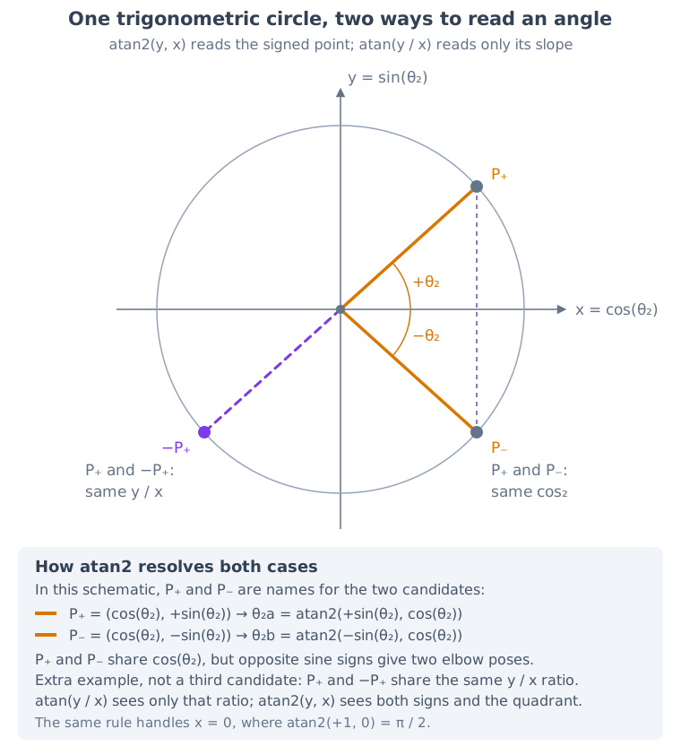
In this schematic, P₊ and P₋ are names for the two elbow candidates used
by the simulation. The separate −P₊ point is an extra example showing how
the same signed-component rule separates opposite directions with the same
ratio.
The solution helper takes one candidate theta2 and calculates the matching theta1 that points the first link toward the requested target. It returns both values together as a complete (theta1, theta2) pair. Calling it with theta2a and theta2b gives us solA and solB, the two full joint-angle pairs that can reach the target.
Both pairs are valid, so the mathematics alone does not tell the simulation which one to animate. We choose the pair that requires the smaller movement from the current pose. There is one detail to handle first: angles wrap around at the to boundary. For example, suppose the current angle is 2.5 radians and a candidate is -2.5 radians. Direct subtraction calculates -2.5 - 2.5 = -5.0 radians, which looks like a large turn of about 286 degrees. On the circle, these angles are on opposite sides of the same boundary, so the joint can instead move about 1.28 radians, roughly 73 degrees, across the wrap point.
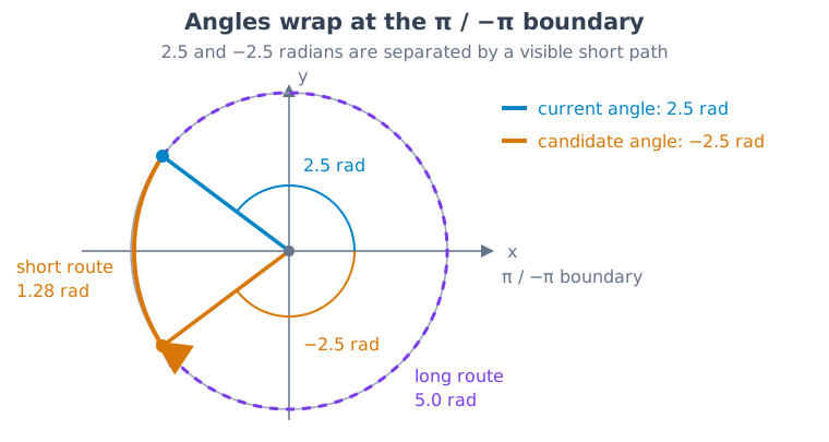
The longer route comes from direct subtraction. Unwrapping lets the simulation compare the shorter route across the and boundary.
The following code addition converts each candidate to an equivalent angle near the current pose, then compares the two pairs fairly:
const solA = solution(theta2a);const solB = solution(theta2b);
function unwrap(angle: number, reference: number) { let a = angle; while (a - reference > Math.PI) a -= 2 * Math.PI; while (a - reference < -Math.PI) a += 2 * Math.PI; return a;}
solA.theta1 = unwrap(solA.theta1, currentTheta1);solA.theta2 = unwrap(solA.theta2, currentTheta2);solB.theta1 = unwrap(solB.theta1, currentTheta1);solB.theta2 = unwrap(solB.theta2, currentTheta2);
const dA = (solA.theta1 - currentTheta1) ** 2 + (solA.theta2 - currentTheta2) ** 2;const dB = (solB.theta1 - currentTheta1) ** 2 + (solB.theta2 - currentTheta2) ** 2;
return dA < dB ? solA : solB;The unwrap helper adds or subtracts full turns of until a candidate angle is within radians of the current angle. This changes only the number used for comparison, not the physical pose, because a full turn brings a joint back to the same direction. We unwrap both angles in solA and solB, so each candidate is represented near the current pose before it is scored.
The values dA and dB measure the required movement for each pair by adding the squared changes of both joints. Squaring keeps the contributions positive and makes a larger movement count more heavily. The return statement makes computeIK choose the pair with the smaller score, so the function returns one complete joint-angle pair instead of both. This is the selection step that keeps the arm close to its current pose instead of switching elbow sides unexpectedly.
With a target and a pair of desired joint angles, the final step is to update the displayed groups during Threlte’s render loop.
Update the joints with Threlte’s render loop
At this point, the code can calculate the desired angles, but it still needs to apply them to the displayed arm. This must happen repeatedly while the simulation is running, because the target or the interpolated joint angles can change from frame to frame. Threlte provides useTask for code that should run during the render loop. We use it to calculate the desired angles and move the displayed angles a small amount toward them on each frame.
function computeIK(x: number, y: number) { ...}
useTask((delta) => { const { theta1, theta2 } = computeIK(target.x, target.y); const interpolation = 1 - (1 - angLerp) ** (delta * 60);
currentTheta1 += (theta1 - currentTheta1) * interpolation; currentTheta2 += (theta2 - currentTheta2) * interpolation;});
</script>The angLerp constant was defined earlier with the scene state, just after currentTheta1 and currentTheta2: const angLerp = 0.15;. It is an animation setting, not a joint angle. The value 0.15 tells the update to move part of the remaining distance on each frame, which makes the arm follow the target smoothly. For example, when delta is about 1 / 60 of a second, delta * 60 is about 1, so the formula produces 1 - (1 - 0.15) ** 1 = 0.15. The current angle therefore moves 15% of the way toward the target angle during that frame. As the difference becomes smaller, each following step also becomes smaller, which makes the arm ease into the target instead of jumping there immediately.
The delta * 60 part adjusts that fraction for the time since the previous frame. At 30 frames per second, one frame lasts about twice as long, so the code takes a larger step. At 120 frames per second, one frame lasts about half as long, so it takes a smaller step. Over the same amount of real time, these adjustments produce nearly the same response, so the arm does not move noticeably faster on a high-refresh-rate screen or slower on a mobile device.
After the two reactive angle variables change, Threlte applies them to the bound rotation.z properties. currentTheta1 rotates the outer group and the first link, while currentTheta2 rotates the nested group and the second link relative to the first. The state update therefore changes the displayed robot pose on the next render.
This is not meant to be a complete robot simulator. It is a compact example of how Three.js provides the rendering primitives while Threlte connects them to Svelte’s component model, state, and lifecycle. The preceding sections explain how the two Svelte components are assembled. The next section collects those pieces into complete files for anyone who wants to copy the example in one go.
Full code
The listings below assume a pre-configured boilerplate project with Svelte, Threlte, Three.js through Threlte, and Tailwind CSS already installed and set up. We are adding the page container and the two Svelte components for the simulation, so project configuration, dependencies, and general styling are not repeated here.
The page places the simulation component inside the same responsive container used by the live example:
<div class="aspect-4/3 w-full"> <RobotArm2DOFMouseFollower /></div>The first component owns the Canvas and mounts the scene component. It is the complete RobotArm2DOFMouseFollower.svelte file:
<script>  import { onMount } from "svelte";
  import { Canvas } from "@threlte/core";  import Scene from "./RobotArm2DOFMouseFollowerScene.svelte";
  let isReady = $state(false);
  onMount(() => {    isReady = true;  });</script>
<div class="relative h-full w-full touch-none" aria-busy={!isReady}>  <Canvas>    <Scene />  </Canvas>
  {#if !isReady}    <div      class="bg-background absolute inset-0 z-10 flex flex-col items-center justify-center"      role="status"      aria-live="polite"    >      <span>Loading simulation...</span>      <span        class="border-contour border-t-secondary mt-4 h-8 w-8 animate-spin rounded-full border-4"        aria-hidden="true"      ></span>    </div>  {/if}</div>
The second component contains the complete RobotArm2DOFMouseFollowerScene.svelte implementation:
<script lang="ts">  import { onMount } from "svelte";
  import { Vector3 } from "three";  import { T, useTask, useThrelte } from "@threlte/core";
  const L1 = 1.6;  const L2 = 1.0;  const CAMERA_FOV = 75;  const CAMERA_MARGIN = 1.08;  const ARM_VISUAL_REACH = L1 + L2 * 1.1 + L2 / 8;  const MIN_CAMERA_Z = 3;
  let target = $state(new Vector3(1.5, 0.5, 0));
  let currentTheta1 = $state(0);  let currentTheta2 = $state(0);  const angLerp = 0.15;
  const { camera, canvas } = useThrelte();
  function fitCameraToArm() {    const rect = canvas.getBoundingClientRect();    if (!rect.width || !rect.height) return;
    const aspect = rect.width / rect.height;    const halfFov = (CAMERA_FOV * Math.PI) / 360;    const requiredZ =      (ARM_VISUAL_REACH * CAMERA_MARGIN) /      (Math.tan(halfFov) * Math.min(1, aspect));
    $camera.position.z = Math.max(MIN_CAMERA_Z, requiredZ);  }
  function updateTarget(e: PointerEvent) {    const rect = canvas.getBoundingClientRect();    if (!rect.width || !rect.height) return;
    const x = ((e.clientX - rect.left) / rect.width) * 2 - 1;    const y = -((e.clientY - rect.top) / rect.height) * 2 + 1;
    const ndc = new Vector3(x, y, 0.5);    ndc.unproject($camera);
    const direction = ndc.sub($camera.position).normalize();    const distance = -$camera.position.z / direction.z;    if (!Number.isFinite(distance) || distance < 0) return;
    target = $camera.position.clone().add(direction.multiplyScalar(distance));  }
  onMount(() => {    const resizeObserver = new ResizeObserver(fitCameraToArm);    resizeObserver.observe(canvas);    fitCameraToArm();
    function onPointerDown(e: PointerEvent) {      if (!e.isPrimary) return;      updateTarget(e);      canvas.setPointerCapture(e.pointerId);    }
    function onPointerMove(e: PointerEvent) {      if (e.isPrimary) updateTarget(e);    }
    function onPointerEnd(e: PointerEvent) {      if (!e.isPrimary || !canvas.hasPointerCapture(e.pointerId)) return;      canvas.releasePointerCapture(e.pointerId);    }
    canvas.addEventListener("pointerdown", onPointerDown);    canvas.addEventListener("pointermove", onPointerMove);    canvas.addEventListener("pointerup", onPointerEnd);    canvas.addEventListener("pointercancel", onPointerEnd);
    return () => {      canvas.removeEventListener("pointerdown", onPointerDown);      canvas.removeEventListener("pointermove", onPointerMove);      canvas.removeEventListener("pointerup", onPointerEnd);      canvas.removeEventListener("pointercancel", onPointerEnd);      resizeObserver.disconnect();    };  });
  function computeIK(x: number, y: number) {    const r = Math.hypot(x, y);    const maxReach = L1 + L2 - 1e-6;    const minReach = Math.abs(L1 - L2) + 1e-6;    const rClamped = Math.max(minReach, Math.min(maxReach, r));
    const cos2 = Math.max(      -1,      Math.min(1, (rClamped ** 2 - L1 ** 2 - L2 ** 2) / (2 * L1 * L2)),    );    const sin2 = Math.sqrt(Math.max(0, 1 - cos2 ** 2));
    // two possible elbow configurations    const theta2a = Math.atan2(sin2, cos2);    const theta2b = Math.atan2(-sin2, cos2);
    const phi = Math.atan2(y, x);
    function solution(theta2: number) {      const theta1 =        phi - Math.atan2(L2 * Math.sin(theta2), L1 + L2 * Math.cos(theta2));      return { theta1, theta2 };    }
    const solA = solution(theta2a);    const solB = solution(theta2b);
    // unwrap relative to current    function unwrap(angle: number, reference: number) {      let a = angle;      while (a - reference > Math.PI) a -= 2 * Math.PI;      while (a - reference < -Math.PI) a += 2 * Math.PI;      return a;    }
    solA.theta1 = unwrap(solA.theta1, currentTheta1);    solA.theta2 = unwrap(solA.theta2, currentTheta2);    solB.theta1 = unwrap(solB.theta1, currentTheta1);    solB.theta2 = unwrap(solB.theta2, currentTheta2);
    // pick closer    const dA =      (solA.theta1 - currentTheta1) ** 2 + (solA.theta2 - currentTheta2) ** 2;    const dB =      (solB.theta1 - currentTheta1) ** 2 + (solB.theta2 - currentTheta2) ** 2;
    return dA < dB ? solA : solB;  }
  useTask((delta) => {    const { theta1, theta2 } = computeIK(target.x, target.y);    const interpolation = 1 - (1 - angLerp) ** (delta * 60);
    currentTheta1 += (theta1 - currentTheta1) * interpolation;    currentTheta2 += (theta2 - currentTheta2) * interpolation;  });</script>
<!-- Lights --><T.DirectionalLight position={[5, 5, 5]} intensity={0.8} /><T.AmbientLight intensity={0.6} />
<!-- Camera --><T.PerspectiveCamera  makeDefault  fov={CAMERA_FOV}  position={[0, 0, MIN_CAMERA_Z]}/>
<!-- Grid --><T.GridHelper args={[10, 20]} rotation={[-Math.PI / 2, 0, 0]} />
<!-- Base --><T.Mesh position={[0, 0, 0]}>  <T.SphereGeometry args={[0.18, 16, 12]} />  <T.MeshStandardMaterial metalness={0.4} roughness={0.6} color="#999" /></T.Mesh>
<!-- Joint 1 --><T.Group rotation.z={currentTheta1}>  <T.Mesh position={[L1 / 2, 0, 0]}>    <T.BoxGeometry args={[L1, 0.15, 0.15]} />    <T.MeshStandardMaterial color="#9bb" />  </T.Mesh>
  <!-- Joint 2 -->  <T.Group rotation.z={currentTheta2} position={[L1, 0, 0]}>    <T.Mesh position={[0, 0, 0]}>      <T.SphereGeometry args={[0.18, 16, 12]} />      <T.MeshStandardMaterial metalness={0.4} roughness={0.6} color="#999" />    </T.Mesh>
    <T.Mesh position={[L2 / 2, 0, 0]}>      <T.BoxGeometry args={[L2, 0.12, 0.12]} />      <T.MeshStandardMaterial color="#b98" />    </T.Mesh>
    <!-- Gripper -->    <T.Mesh position={[L2 * 1.1, L2 / 10, 0]}>      <T.BoxGeometry args={[L2 / 4, L2 / 10, 0.12]} />      <T.MeshStandardMaterial color="#de6d00" />    </T.Mesh>
    <T.Mesh position={[L2 * 1.1, -L2 / 10, 0]}>      <T.BoxGeometry args={[L2 / 4, L2 / 10, 0.12]} />      <T.MeshStandardMaterial color="#de6d00" />    </T.Mesh>  </T.Group></T.Group>
<!-- Target marker --><T.Mesh position={target.toArray()}>  <T.SphereGeometry args={[0.04, 12, 8]} />  <T.MeshStandardMaterial color="#ff6666" emissive="#330000" /></T.Mesh>